Super Mini-Node Interface Card (SMINI) - Part 1
페이지 정보
작성자 Jenna 작성일24-05-23 09:58 조회12회 댓글0건관련링크
본문
It has the capability to replace multiple pressure measurement devices on a loadlock with its absolute pressure measurement from atmosphere to 10-8 Torr and atmospheric switching capabilities. Additionally, in every case, the RS422 or the RS485 full duplex implementation is used to make the "daisy-chain" connection between multiple nodes. This connection may be used to limit the common-mode signal that can be impressed on the receiver inputs. SC, G or reference, the common signal reference ground used by the receiver to measure the A and B voltages. 5Vdc, unless the corresponding segment of SW2 is closed, switching the line to ground. Line A voltage, implying A, the green wire, is indeed connected to the driver inverting signal, as seen in a whitepaper. With Modbus, BACnet and Profibus, A/B labeling refers A as the negative green wire and B as the positive red wire, in the definition of the D-sub connector and M12 circular connector, as can be seen in Profibus guides.
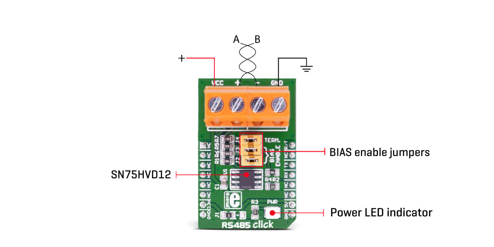
Axis Fuse (1-4) - These green LEDs are lit whenever a corresponding axis is enabled and power is being applied to an axis motor. Using less resistance is not good, because lower values do not adequately limit current surges resulting from the capacitor being discharged when the input line is switched to ground by the external hardware. Only one output line is illustrated because all are identical. U6 and U7 are identical RS485 transceiver ICs capable of transmitting and receiving over the same 2-wire transmission line to support half-duplex operation - two wires transmitting bi-directionally. The diagram below shows potentials of the A (blue) and B (red) pins of an RS-485 line during transmission of one byte (0xD3, least significant bit first) of data using an asynchronous start-stop method. You also avoid the need of an oscilloscope to check for the direction of data flow and the possibility of device failure causing bus contention whereby data tries to flow in both directions simultaneously on the same pair of wires. Each SMINI and SUSIC includes an adjacent pair of RS485 pins making the daisy-chaining easy to accomplish. This setup facilitates easy daisy-chaining from node to node.

The SMINI provides everything required to set up a very capable node on a single card, at a very reasonable cost. This combination provides a complete system node with 48 outputs and 24 inputs on a single card. Connectors There are 15 connectors on the system used for, motor, limit, training, laser, interlock, power, and communications connections. Circuits may be terminated on screw terminals, D-subminiature connectors, or other types of connectors. If you have purchased your SMINI already assembled and tested, you may skip to Computer Connections. If you happen to have one of these early SMINI cards simply ignore the 1, 2 and 3 printing on the card and treat them as if they read 0, 1 and 2. See section Counting Cards/Nodes Using Number Zero in Chapter 2 for change in approach. Software is used to define the latch output, and therefore we have total control of the load’s operation. A disadvantage of software filtering is that it does require extra processing time, therefore slowing down your real-time loop.
However, for most C/MRI users, myself included, I do not recommend employing software filtering. However, just because the 4-wire arrangement has the capacity for supporting simultaneous communication in both directions, it does not mean that the capability is always utilized, as is the situation with the C/MRI. The typical multi-node setup is illustrated in Fig. 4-1b. Fundamentally, every multi-node application requires that all nodes, plus the connection leading toward the computer, need to be "daisy-chain" connected using RS422/485, a 4-wire cable. Alternatively, if your computer has USB only, then you will need to incorporate either a USB to RS232 Converter Cable between the computer and the RS485 card or a USB to RS422/485 Converter Cable connected between the computer and the RS485 header on the SMINI or SUSIC. It requires a single 3-wire RS232 cable to connect between the computer’s RS232 serial port and the RS232 header on the SMINI or the SUSIC. The only requirement for connecting the C/MRI is that your computer has an RS232 serial port and/or a Universal Serial Bus (USB). The SMINI and the SUSIC can make use of four interface standards: Universal Serial Bus (USB), RS232, RS422 and a "full duplex" implementation of RS485.
For more information regarding RS485 standard visit the web page.


